SOLILOQUY
The Soliloquy mono power amplifier is the fruition
of over 20 years research into discrete linear amplifier and power regulation
circuits to produce the most sophisticated, technologically advanced solid
state amplifier ever built.
<<INTERNATIONAL
REVIEWS>>
What the critics say...
" So neutral though, is the
Metaxas Opulence/Soliloquy set up that I could have used just about any
sources I liked once the interconnecting cables were sorted. All I'd be
hearing were the individual characteristics of the source components. However
neutral or 'naked' the sound, the MAS doesn't come off as 'transistory'
or clinical ... it had a feather-light touch and a way with tiny details
that suggest either a pedigreed 60W or 70W per channel tube amp of recent
vintage ..."
Ken Kessler, HI FI NEWS& RECORD REVIEW,
England.
" It would make a perfect tool to assess equipment by. If any component
is not in the top league, the amps will betray the culprit with surprising
honesty. Its other great strength is the speed of delivery. It can keep
up with the fastes of guitar runs and tambla rolls with a speed normally
associated with single-ended valve amplifiers".
Alan Sircom, HI FI CHOICE, England.
 THE SOLILOQUY
Starting its commercial life as the MAS A2 amplifier in 1983, it has been
continually refined as faster output transistors and better components
have become available.
In its present form, each channel is made up of essentially five complete
amplifier circuits, encompassing the linear gain input stage with high
current output stage and four amplifier circuits whose role is to supply
an absolutely stable voltage and current source irrespective of A.C. line
condition.
The U.H.F. and R. F. circuit board techniques have been essential to ensure
that the amplifier is unconditionally stable into any known loudspeaker
load, including inductive electrostatics or low impedance ribbons.
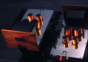
Construction is similar to the MAS SOLITAIRE except that only one channel
is housed per enclosure. The massive 2 Kilowatt grain-oriented steel transformer
features 2 separate secondary windings to ensure that the high current
output stage does not affect the low current input stage. All connectors
are of the highest quality, and every component, including the 86,000uF
computer grade capacitors is bolted onto the single printed circuit board
for ease of servicing and to maintain the shortest possible signal path.
OPERATING INSTRUCTIONS
Connection of the SOLILOQUY into a typical system is relatively straight
forward since it possesses only a set of inputs (which are connected to
the respective channels of the preceeding preamplifier) and a set of speaker
Terminals (Red and Black to indicate correct polarity).
1. Ensure that the ON/OFF switch on the FRONT PANEL is in the 'OFF' position
whilst connecting the SOLILOQUY into the system. Once connected, ensure
that there are no 'short circuits' in the speaker wires, then preceed to
switch the system 'ON'. For best sound results, it is recommended that
the unit is preheated for at least 15 minutes, before critical listening.
TECHNICAL DESIGN
Input Impendance
The 130kOhms/82pF input impendance using BIPOLAR inputs, ensures that there
are no loading effects to the output stage of the preceeding Preamplifier
and severe H.F. roll-off with long interconnect cables. We use direct wiring
to electrically connect the input to the Main Circuit Board.
Power Supply
The SOLILOQUY uses one of the most sophisticated, over designed Power
Supply systems in a commercial amplifier.
Transformers: Each chanel sports a 1,600 Watt continuous transformer
with 12 Amps continuous current capability to the Output Stages and 2 Amps
to the Input Stages.
Primary
Filtering: This is then bridge rectified and fed to the +/-33,000uF Filtering
Supplies for the OUTPUT STAGE and the +/- 10,000 Filtering supplies for
the INPUT STAGE. The Voltage Gain Stage and Output Current Gain Stage operate
independently.
Voltage
Regulation: The Regulation Circuits are formed by totally discrete, high
speed bipolar devices (42 matched and selected devices), which differ only
in their 'Series Pass' transistors based on the current requirements. The
Output Stage Regulators use the same ultra-fast Bipolar Power Transistors
as used in the Output Stage, with it's of 60 Megahertz and current capabilities
of 12-15 Amps smaller Power Device with higher Master Circuit' features
purely differential sensing elements with active current loading and a
precision voltage reference. The negative circuit tracks the Positive 'Master'
to ensure balanced operation under all condition. These circuits ensure
ripple-free totally symmetrical and stable DC which is unaffected by current
demands.
Voltage Amplifier
The Input Stage of the SOLILOQUY features a pure complementary cascoded
differential BIPOLAR Stage with constant current regulating the biasing
current. The devices utilise a considerable amount of 'emitter degeneration'
(local feedback) which increases their input impendance, linearity and
large signal slow rate. The second voltage gain stage utilises complementary
cascoded high speed BIPOLAR devices which drive their quiescent biasing
from the input stage current source. The voltage amplifier consumes 12
selected and matched devices.
Current Amplifier
(Output Stage)
The Output Stage of the SOLILOQUY features a complementary Darlington Stage
Triple idling at 30w in the Class A mode and switching to Class AB up to
100w. This biasing maintains the optimum heating temperature for the Power
Devices to yield their maximum bandwidth and HFE. It utilises ultra fast
(60 MegaHertz) Bipolar Devices which have low input capacitance (100pF)
and high current capabilities (12-15 amps each). These devices eliminate
the need for output ZOBEL networks, INDUCTORS or lag compensation normally
required to slow down the input stage for use with slower BIPOLAR (3-5MHz)
or MOSFETS (10-13MHz).
Protection Circuits
The SOLILOQUY features two modes of protection - one which is inherent
in the operation of the design which acts as 'current' protection and the
other which uses associated sensing circuitry to monitor the outputs for
DC and deactivate if DC is present.
If a high current condition arises, the positive supply fuse (5A fast blow)
will preferentially blow instead of the negative fuse (4A fast blow). Because
the negative supply 'tracks' the positive, if the positive fuse blows,
the negative supply will always symmetrically discharge to avoid the possibility
of DC voltage from reaching sensitive speakers.
If a DC voltage is sensed at the output (greater than 0.6V) a relay in
series with the output will open until the condition is rectified.
Serviceability
The complete Active circuitry of the SOLILOQUY including the Regulation
Circuits and Primary Filtering Capacitors are all mounted to the large
single ground plane P.C.B. Easy access to the board is maintained by simply
removing the lid to gain access to the 'component side' or the base to
gain access to the 'underside' (the 'track' side) to change a blow fuse
etc. The board slots into the two side panels which are extruded from thick
aluminium and are also used as part of the heat sink assembly. The output
devices are bolted to the two sides. To remove the complete module for
returning to the factory is very easy - simply remove the mounting bolts
holding the heat sink assembly, the four bolts holding the back panel,
desolder the transformer from the main board and slide the whole assembly
out including the input and output terminations.
Service Details
To be carried out only by accredited M.A.S. Service Personnel. Unauthorised
servicing will result in cancellation of Warranty.
Amplifier Breakdown
The SOLILOQUY was designed to be inherently self protective if externally
abused. If a short circuit condition arises, there are three steps of protection.
1. A 5A Fast Blow fuse on the positive supply to the output stage regulator
(the 'Master Circuit'). If a short circuit condition arises, this fuse
will preferentially blow resulting in discharging of both positive and
negative supplies so that there is no DC present across the speaker terminals
which would destroy speakers. The negative fuse (4A s low blow) will only
blow in severe cases. The negative supply tracks the positive supply, so
when the fuse blows and the voltage or the positive supply starts decreasing
the negative follows suit.
NOTE: Before replacing the 5A fuse, it is necessary to discharge
the filtering capacitors with a 100 Ohm 5Watt resistor for 10 seconds to
eliminate any sparks that can arise when replacing the fuse. The hear discharge
can burn fingers, so please hold the resistor with pliers.
2. The 0.51 Ohm 5Watt 'Emitter Resistor' will 'open circuit', so if when
reinstalling the fuse and you find no voltage after the regulator circuits
(45V DC), these resistors must be replaced. You can measure them with a
multi meter.
3. The 'Series pass' transistors will 'short circuit'. If you measure a
low resistance between the collector and base or emitter (less than 100
Ohms), you must replace the transistors. This is if a High Frequency transient
(using cables which have the centre pin connecting but not the outer GND)
is accidentally applied to the amplifier.
Steps for Servicing
1. Check all connection cables for open or short circuits.
2. Remove lid and inspect the INPUT STAGE (1/2A Fast blow) and OUTPUT STAGE
(5A Fast Blow on positive, 4A Slow Blow on negative) for blown fuses.
3. Replace blown fuses and check voltage.
OUTPUT STAGE : at fuse holders - +/- 53VDC (+2.5V)
after regulators - +/- 45VDC (+1V)
INPUT STAGE : at fuse holders - +/- 60VDC (+2V)
after regulators - +/- 48VDC (+1V)
Ensure that the negative is tracking the positive after the regulator circuits
(within 0.5VDC).
4. If the voltage after the regulators is not measurable, replacement of
the 0.51 Ohm 'Emitter Resistors' will be necessary. This can be done without
removing the board from the amp case. Measure the four resistors with a
multi meter.
5. If the problem is still apparent after replacing the Emitter resistors,
then the transistors may have blown. Use multi meter to measure the resistance
between the Collector/Base, Collector/Emitter. (These should measure greater
than 100 Ohms or even higher).
If these steps have not rectified the problem, the module should be removed
the case for servicing by qualified personnel, or shipped back to M.A.S.
6. TO REMOVE THE MODULE
a. First desolder the transformer connecting cables from the P.C. board.
b. Desolder the mains wire which attaches to the rear I.E.C. socket.
c. Unscrew the bolts holding the Heat sink bracket and Heat sinks to the
side panels.
d. Unscrew the bolts holding the back panel to the side panels.
e. Slide out complete module with back panel.
The module is now free for further servicing, or for shipment to M.A.S.
Australia.
Biasing of the SOLILOQUY Module
After the SOLILOQUY module is fully assembled and tested, it is then
'BIASED' whilst installed in its HEAT SINK ASSEMBLY before being installed
into the MAIN CASE. There is one trimpot which facilitates the biasing
of the quiescent current of the output stage.
NOTE: Ensure that the trimpot is adjusted fully anti clockwise (18 turns).
Biasing of the Output Stage
1. Connect DC supply before the Output Stage Regulator Circuits as
well as the Input Stage Regulator Circuits. Ensure that this Trimpot is
initially in the maximum anti clockwise position.
2. Connect multi meter across one of the 0.51 Ohms 5W Output Resistors
(not the regulator resistors, but OUTPUT STAGE resistors). One side of
the resistors is connected to the RED Speaker Terminal, so this could also
be used as an anchor point for one of the probes.
3. Slowly turn the TRIMPOT in the clockwise direction until 0.05VDC is
measured across the resistor. Maintain for thirty minutes.
This module is then biased for approximately 15W Class A mode.
CHECKING THE MODULE AFTER SERVICING
Test Instruments Required: MULTI METER and +/- 30V DC CURRENT LIMITING
POWER
SUPPLY.
1. Visually inspect the top and underside of the PC Board for any conductive
debris which can be shorting out connections.
2. Ensure that the Biasing Trimpot is in the fully anti clockwise position
and that all the fuses are removed.
3. Connect the DC Supply (observing correct polarity) across the Input
Stage only. Set the positive supply to approx. 25V DC output and the negative
to 30V DC output. This will test the negative tracks the positive. Program
for 100mA - 200mA current limiting, then switch on. There should be no
current limiting and the negative should be tracking the positive after
the regulator circuits.
4. Repeat with Output Stage regulator only.
5. If both negative regulators are operating correctly proceed back to
the Input Stage Regulator and remove the GND connection from the DC supply
and in its place, correct the negative wire. This is to put at least 55V
DC across the Positive Regulator to ensure that it is functioning correctly.
When switching on, the voltage should be between 48 and 50 volts DC after
the regulator.
6. Repeat with Output stage (independently - do not do both at the same
time). This time the reading should be between 44 and 46V DC.
7. Connect a link between the regulator and adjust the external current
limiting power supply to 200mA/+/- 30VDC. Because there is not enough voltage
to turn the DC RELAY on, monitor the output after the 0.51R emitter resistors.
You should now be able to monitor the correct operation of the amplifier
on switch on except for some crossover.
Regulator Voltage Adjustment
The output stage regulator should never require adjustment, but if
repairs have been made to the INPUT STAGE REGULATOR, it might need adjustment.
Monitor the output voltage after the regulator to see whether it falls
between the acceptance range of 46VDC - 48VDC.
To effect an adjustment, you must TRIM the resistor R154 until the correct
output voltage is achieved.
Specifications
FREQUENCY RESPONSE : DC - 1.0MHz (-3dB) dictated by input filter
(without filter 10 Mega Hertz).
POWER OUTPUT : 100WRMS per channel into 8 Ohms with no
more than 0.05% T.H.D.
DYNAMIC HEADROOM: 0dB due to stiff regulated Power Supply
DAMPING FACTOR: Greater than 500 wideband
SLEW RATE: Greater than 1000V/us small and large signal
T.H.D. : Less than 0.05% wideband
I.M.D.(S.M.P.T.E.): Less than 0.05% wideband
SIGNAL/NOISE : -117dBV unweighed input shorted
SENSITIVITY: 0.08VRMS in for 100w out (28dB)
INPUT IMPEDANCE : 130kOhms in parallel with 82pF
home!