SOLITAIRE
The Solitaire combines two completely dual-mono ultra high-speed power amplifiers onto one chassis, sharing only the large 1600 WATT laminated transformer to produce over 100 WATTS per channel from DC to well over 500kHz into any known speaker load with absolute stability.
<<INTERNATIONAL REVIEWS>>
What the critics say...
Listener A "There is not much else to say except that the SOLITAIRE leaves far behind our best references".
Listener B " Let's get straight to the point; MAS electronics are more than surprising, they are a real discovery, a rare find. Rarely have we heard on transistor units such liquidity, such an ease of reproduction where voices once again find melody and softness'
Jean Hirage/Patrick Vercher LA NOUVELLE REVUE DU SON, France.
" The Solitaire is yet another solid state amplifier that I liked from the first time I heard it in my system. It passed very musical and unharsh sounds through to the speakers. Its sound is characterised by exquisite spatial presentations, solid dynamics, great transparency and a tonality that is a little soft sounding in the high frequencies. This amp is lyrical and quick sounding.
A Bascom H. King thumbs up for this one!"
Bascom King, AUDIO USA.
" The conclusion: the sensation is perfect. A power Amplifier for 9000DM can reach without problems to the position of ABSOLUTE SPITZENCLASSE and is immediately equal to competitors that are three times more expensive".
Alexander Strobel, STEREOPLAY, Germany.
" This amplifier, once it stops pouting and stamping its feet, has definition, transparency, clarity and solidity which will charm the pants off anyone who regards imaging and detail retrieval as paramount".
Ken Kessler, HI FI NEWS &RECORD REVIEW, England.
" The Solitaire is more impurtable, more steady, more precise and subsonically more tremendous than any SUMO power station of mulitple power output. Furthermore, the Solitaire isn't picky at all with speaker principles. A complex dynamic 4 way speaker like Infinity Kappa 8, it brings the amp to top performance as do the extremely difficult electrostatic speakers of Putz or the old Martin Logan CLS. The real astonishment is met, however if one connects against all odds, the Metaxas power amp with the brilliant 300DM loudspeaker like the Energy Point 1E. Then the Canadian shoe box sounds immediately like a noble speaker of ten times the price, surprises with bass extension, midrange resolution, transparency and easiness of treble ... "
Ulrich Michalik HI FI EXCLUSIV, Germany.
" A pampered Solitaire will produce a vast soundstage with easily descerned and clearly positioned borders, with the musical event placed solidly in its own, uncompromised space and despite its sledgehammer slam, the Solitaire is capable of separating the brutal from the delicate, preserving the relationship between notes at either end of the dynamic frame".
HI FI CHOICE GUIDE TO HIGH END , England.
"The poweramp specifically had no difficulty driving loads, even of the B&W 801FS and Analysis type (Greek, Apogee clones). In all other aspects the combination is very relaxed, with excellent plasticity and three dimensional body, excellent descriptive ability of the recording location (especially with the Celestion Kingston) and equally good rendering of the air.The performance of various frequencies can, in two words, be described as extremely homogeneous. You will not be able to tell them apart in well recorded material, with able three way transducers. Such a composure exists! The bass is very quick with top grade body and attack, not slowing at all. The mids are very descriptive, with very good detail and purity, soft and extremely sweet. The highs are delicate, with excellent body and special plasticity. The stereo image has excellent dimensions and very good "black" character, and by saying this, I mean the "black" space that separates the instruments and makes them sound as separate entities, with lifelike positioning in space, in well recorded material."
Thanassis Moraitis, SOUND & HI FI ,ATHENS, GREECE
.........................................................
SOLITAIRE
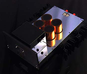
Constructed from a combination of anodised aluminium bar for the front and side panels with stainless steel plates on the top, bottom and rear plates, the SOLITAIRE epitomises the state of the art in audio industrial design - where technology heads into the realm of art.
The rear panel supports our custom designed RCA inputs and binding posts and every other component including the output transistors, are directly soldered to the single, dual-mono printed circuit board. The board becomes one large module which can be quickly and easily removed to facilitate any circuit updates or servicing requirements.
By shortening the signal path wiring to only 50mm from input to output including the current path from the massive transformer to the high-speed bipolar output devices, the SOLITAIRE allows a transparency of reproduction which is only limited by the associated equipment in the audio system.
1. INPUT STAGE: The fully complementary, dual differential, cascaded input stage is linearised to ensure least distortion over the large voltage swings to the amplifier input from the preceeding preamplifier. A very gradual (6dB/octave) Bessel filter is incorporated at the input to eliminate the needless reproduction of Radio Frequencies.
The second voltage gain stage uses considerable local feedback to ensure that large voltage swings from the input stage are accommodated with the least possible distortion.
An overall negative feedback of only 11dB is required to stabilise the complete D.C. operating point and reduce distortion at full power to below 0.1% T.H.D. which is primarily composed of second harmonics.
A D.C. servo is built around an integrated circuit to monitor the output voltage and ensure absolute D.C. stability at all times.
2. OUTPUT STAGE: Our triple Darlington output stage uses conventional thermal feedback techniques to eliminate thermal runaway. Our printed circuit design borrows techniques from RF and UHF ground plane technology to maximise the speed of current delivery, especially at high frequencies, from the ultra high-speed (fT's 80 MHz) power transistors used in the output stage. There are absolutely no output stability networks (inductors or zobels) in the signal path.
3. POWER SUPPLY -
INPUT STAGE: The input voltage gain stage of the SOLITAIRE is isolated via the high-current output stage via a two stage 'capacity-multiplier' circuit which uses the beta of the transistors to multiply the filtering effect of the capacitor used. The simplicity of this circuit allows the elimination of any output bypassing capacitors which would otherwise reduce the apparent speed and degrade the sound quality of this amplifier.
OUTPUT STAGE: Our unique concept of paralleling high-speed rectifier diodes instead of the traditional brute force, high-current rectifiers magnifies the effect of using low impedance 66,000uF computer grade capacitors in conjunction with the 1600 WATT continuous power transformer to give the impression of a far more powerful amplifier - especially in the high frequency ranges where the current delivery is far more instantaneous.
4. PROTECTION CIRCUITS: To eliminate the sonic colourations imposed by sophisticated current limiting protection circuits, the SOLITAIRE uses only the short M205 fuse types to protect the high current stages.
Apart from the fuses is a four pole relay in series with the loudspeaker connections. If over 0.6VDC is sensed at the amplifier output, the relay is activated until the condition is rectified.
...................................................
OPERATING INSTRUCTIONS
Connection of the Solitaire into a typical system is relatively simply since it possesses only a set of inputs (which are connected to the respective channels of the preceeding preamplifier) and a set of speaker terminals, red and black to indicate correct polarity.
Steps for connection:-
1. Ensure that the ON/OFF switch on the front panel is in the OFF position, whilst connecting the Solitaire into the system.
THE OFF POSITION IS WHEN THE LEFT HAND SIDE OF THE ROCKER SWITCH ON THE FRONT PANEL IS DEPRESSED.
BY DEPRESSING THE RIGHT SIDE, YOU SWITCH THE AMPLIFIER 'ON'.
2. Once connected, ensure that there are no short circuits in the speaker wires, then preceed to switch the unit ON.
Note. For best results, it is recommended the the unit is preheated for at least 15 minutes, before critical listening is attempted.
Protection Circuits
The output stage of the Solitaire is fused with +/- 4A fast blow fuses which protects the amplifier in case of operating faults.
DC protection os also featured which disables a relay if a DC signal is sensed or the power supplies are interrupted (If a fuse blows).
Serviceability
The complete active circuitry of the Solitaire is mounted to the large single ground plated, printed circuit board. Easy access to the board is maintained by simply removing the lid to gain access to the 'component side' or the base of the case to gain access to the underside (the track side). The fuses are easily accessible on the 'component side'.
SOLITAIRE
SERVICING INFORMATION
Testing the Module.
(Please note that when connecting the SOLITAIRE into a 'test system', that there is insufficient voltage to switch on the output relay, so the output leads must be connected to the black speaker terminal AND the transistor emitter resistor (0.47 OHMS 5W W/W).
1. Connect the + and - supply lines to an external current limiting Power Supply with max. +/- 30VDC output voltage (or use 2 x 3 30VDC supplies).
2. Rotate the biasing trimpot fully 18 turns anti clockwise.
3. Connect the amplifier to a signal source (sound tech 1700B or oscillator) which generates sine wave at 1.0kHz frequency and monitor the input and output on a dual trace oscilloscope.
4. Power the module on and check that there is no current limiting. You should be able to monitor the amp on the oscilloscope. You should see a ave with severe crossover distortion.
5. Measure the voltage drop after the 'capacity multipliers' which should be 2 volts less than the main voltage of 30VDC. If either the positive or negative devices drop more than this voltage, check their VBE and ensure that it is not more than 0.65V. If a higher value is measured, replace the device.
6. If the voltages are O.K. check the waveform on the osc. It should show crossover distortion.
7. Clip a multi meter across 0.47 OHMS 5W wire wound output stage emitter resistor and turn the trimpot clockwise until you measure approx. 0.0125V across this resistor.
SERVICING INFORMATION
If a fuse blows:
1. Measure the resistance (100R setting on FLUKE 8050A) of the power and driver
transistors between all 3 terminals. If any reading is less than 100R the listed devices must be replaced. Q1-10 and Q101-110.
2. If necessary, remove the module from the chassis and return to M.A.S. or accredited servicing agent.
TESTS:
1. DC PROTECTION CIRCUIT: To check the correct operation, connect a 'DC Source' - a battery, etc, across the BLACK speaker terminal and at the junction of the 1.0 MEGA OHM R53 or R153 /0.22 mF C13/C113 input network which is closest to the TL072/LF353 I.C.
Please note that if you connect it to the wrong side - the output of the amplifier, it acts as a short circuit and can destroy the amplifier!
2. DC SERVO: Using a high quality multi meter, measure the DC offset between the BLACK and RED speaker terminals. It should be around 0.002 VOLTS or less. If it is more than 0.05 VOLTS, the TL071 I.C. should be replaced.
3. OUTPUT TRANSISTOR BIASING: The SOLITAIRE has 4 pairs of output transistors and when 'biasing' the amplifier it is wise to check the biasing of ALL the output transistors to ensure that one or more of the devices are not conducting more current than the others. This is especially important when replacing a power transistor. Also check the different biasing currents between the NPN and PNP devices. If there is a large discrepancy, replace the 'driver transistor' (also mounted to the heat sink).
VOLTAGE CHECK
VOLTAGE FROM MAINS SUPPLY. Can be measured at the FUSE HOLDERS or the COLLECTOR (middle pin) of either the Power Transistors or Driver Transistor.
Depending on the country and mains voltage fluctuations, this voltage should range a minimum of 55VDC - 60VDC.
VOLTAGE AND INPUT STAGE. This tests that the "CAPACITOR MULTIPLIERS" are correctly functioning.
Measure across the metal can collectors of the transistors Q24/Q11, Q26/Q12 and Q124/Q111, Q126/Q112.
The voltage drop should be approximately 2VDC.
VOLTAGE ON OUTPUT TERMINALS
Place you probes across the speaker terminals and measure less than 0.05VDC. If the DC Protection circuitry is operating, you must measure this voltage between the BLACK speaker terminal (EARTH) and the junction of resistors R101/102/103/104/105/106/107/108 on the PC Board (ie., before the relay).
BIASING VOLTAGE refer to SOLITAIRE MANUAL.
POTENTIAL PROBLEMS OR FAULTS
1. Blown outputter Driver transistors. This can happen because:-
a. Incorrect connection of interconnect cable (common problem is a "floating ground connection").
b. Short circuiting the output terminals.
PLEASE NOTE: In many cases, when a fault arises, it is only ONE transistor which may be damaged. Using a multi meter, measure the impendance between any two pins (CE, CB, BE) until you find the device with the lowest resistance. Remove this device OUT OF THE CIRCUIT, then measure the other transistors again. If their impendance is greater than 100 Ohms, they are okay.
2. Blown Input Stage Transistors.
This fault can arise and will manifest itself as an amplifier which will not function on the test bench. Simply measure the VBE of the input stage devices and confirm that this sis the problem. Then replace these devices with matched sets of devices supplied by the factory.
3. Faulty DC Protection Circuit.
a. Measure voltages to U2/U12 to ensure that power supply is not at fault.
b. Replace MPSA06's if U2/U12 seem to be operating correctly.
4. Biasing Trimpot Has No Effect.
Replace Q13/Q113.
IF FAULT PERSISTS:
Remove complete module, including heat sink bracket and back panel (RCA inputs etc) and return to factory for repair.
UPGRADE MODIFICATIONS:
The latest version of the SOLITAIRE MARK 3 has the following improvements over Mark 1 & 2 Models:
1. Soft turn-on/turn-off circuit.
This is accomplished by adding a simple network of two rectifier diodes and a 100uF capacitor to power on the output protection relay. A large 5.6KOHMS 10W WW resistor is wired on the mains to enable plus/minus 6-10VDC to reach the four large electrolytic capacitors- essentially charging them so that the "turn-on current rush" is minimised. Also, the 100uF capacitor discharges faster on turn-off so it disconnects the speakers from the amplifier immediately after the amplifier is turned off.
2. AC WIRING I.E.C. Connector is now beside the large transformer stack so it does not interfere with the low-level signal part of the amplifier.
3. DC SERVO changes: The time constant is slightly changed to replace the polypropylene capacitors with polystyrene types: 0.22uF/1.0 Meg replaced with 10,000pF/10Meg.
4. Input wiring: replaced with ENOSIS wire.
Specifications
FREQUENCY RESPONSE: DC - 1.0MHz (-3dB) dictated by input filter (without filter 10 Mega Hertz).
POWER OUTPUT : 130WRMS per channel into 8 Ohms with no more than 0.05% T.H.D.
DAMPING FACTOR: Greater than 500 wide band
SLEW RATE: Greater than 1000V/us small and large signal
T.H.D.: Less than 0.05% sideband
I.M.D.(S.M.P.T.E.): Less than 0.05% sideband
SIGNAL/NOISE: -117dBV unweighed input shorted
SENSITIVITY: 0.8VRMS in for 100WRMS out (28dB)
INPUT IMPEDANCE: 130kOhms in parallel with 82pF
home!